Starting
EEC from Scratch
So you want that new fangled EFI thingy huh?� EEC-IV might not be what you want; EEC-IV is
the best �Factory� option we have but there are many different Fuel Injection
systems out there.� If you want to retain
your cars every day streetabilty there are limiting factors that you will run
into.� Having a Mass Air Flow sensor is
important for an every day streetcar.� As
you push more power into your engine you will find that it will be harder and
harder to retain good streetabilty.�
Larger injectors, big cams, high octane, stand-alone computers, and race
transmissions will all be in the cards down the road for racecar power.� Big power engines are easier to control with
Speed Density, and for those interested Ford made a few EEC�s SEFI and Speed
Density.� Remember compromise, write out
a list of your goals, and see what it takes to achieve them.
|
Stock Engine |
EEC-IV |
|
Stock Engine w/ Mild changes |
EEC-IV MAF |
|
Stock Engine w/ Mild changes and Electronic Transmission |
EEC-IV MAF that has trans control ability * |
|
Engine with �
Stroker kit �
Nitrous �
Blower �
Other High Power Adders |
EEC-IV w/ Chip |
|
Engine with �
Stroker kit �
Nitrous �
Blower �
Other High Power Adders And Electronic Transmission |
EEC-IV w/ chip And a separate trans controller * |
|
Engine w/ Big mods and you plan to add power builders
monthly |
Aftermarket Computer |
|
Stock Modular Engine Electronic Trans and other current
features |
EEC-V |
|
Modular Engine w/ mild mods Electronic Trans and other
current features |
EEC-V w/ Chip |
|
* There are currently 3 choices
for trans controlling �
Run a stock engine and trans with EEC-IV �
Run the engine off one computer and the trans off a second
EEC-IV �
Use a TCS controller for complete control of trans operation |
|
In my opinion you have two options.� Stock engine and matched EEC-IV, or plan the
engine you really want and have your EEC customized to it.� But there is always other ways to do it and be
successful.� The very first thing to do is get a lot of
information about your vehicle, was there ever an EEC-IV offered?� That�s the best EFI swap for you.� If EFI was never offered, snap a picture of
your engine bay and take notes your engine size, location, and possible
interference.� Take that picture and look
on-line, in magazines, and in junkyards for parts that will fit into your
engine bay.� Try to find a setup that was
offered on your engine.� The easiest way
is to find a donor vehicle for the parts or complete engine if you dare.� If you can get the EEC to match the
displacement of the engine you�re building, I can guide you to wiring the
injectors to match the firing order.� If
you want to go with high performance aftermarket parts, read this page then go
into modifying EEC-IV for better parts.�
This is a small list of donor vehicles:
�
5.0L
Speed Density 1985 to 1988 Mustang
�
5.0L
Mass Air 1989 to 1993 Mustang
�
5.0L
Speed Density 1987 to1990 Crown
�
5.8L
Speed Density 1987 to1990 Crown
�
5.8L
1987 to1993 E or F truck or van
�
5.0L
1987 to1993 E or F truck or van
�
7.5L
1987 to1993 E or F truck or van
� �4.9L 1987 to 1993 F truck
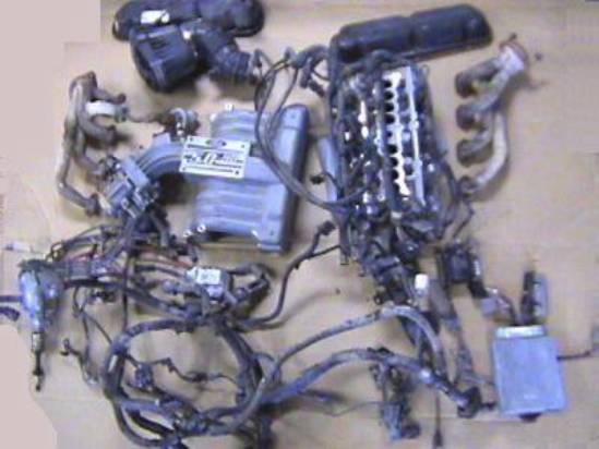
Above is a picture of what you will need out of the donor vehicle, you can
also get these items used off the internet, from swap meets, or give us an
e-mail for help, just look for a good deal.�
This is a list of what you will need to do the conversion, try to get as
much of it from the donor vehicle as possible even if you�re going to replace
it.� If you are upgrading don�t re-buy
brackets you already have unless you are adding high performance aftermarket
chrome stuff.
�
Upper and lower
intake manifolds.� Ensure they are
complete but I recommend replacing everything but the fuel rails and throttle
body.
�
O2 sensor
harness, you can buy new bungs to be added to your exhaust
�
�
Distributor for
new TFI and an E-Coil
�
EEC-IV Computer
�
If you have
found an EEC and are unsure of its application.�
Look at this small list of different EEC Calibration Codes and the vehicle it was originally used on
�
If you are wandering
the junkyard for EEC�s and want to know where Ford hid them in a car, look at
the EEC Locations page.
�
High Pressure
fuel pump
�
High pressure
fuel line and filter
Preparation
Get
all this home and clean it.� Use
scrubbers, sandblasters, parts washers, hot tanks, and don�t be afraid to trash
stuff that seems beyond repair.� You and
I both want this set-up to last you another 20 years with only small
maintenance issues.� Now get your vehicle
somewhere safe, dry, and warm, take off everything prior to the cylinder
heads.� We�re talking from the intake to
the air cleaner, remove the fuel pump and under hood fuel lines.� Find a place to mount the EEC-IV, I hope you
found a place inside the vehicle. Some think it is ok to mount it under the
hood, but this is my web site and we talk about the best way to do things
here.� I�ll let you ride 3 blocks in my
engine compartment and ask how you liked it!�
Your engine has coolant, an air filter, and rubber engine mounts, little
EEC doesn�t have any of that.� Shouldn�t
that EEC be mounted in a safe place, like in the same place you�re riding?�
Install
the injectors, fuel rail, and sensors prior to installing the lower intake
manifold on the engine. �Decide on
location for the solenoids that control EGR and smog pump systems.� Also find a place for the fuel pump, EEC, and
A/C relays and the fuses to power them.�
This is when you need to plan the routing of the harness.� You don�t have to worry about
the harness construction yet, but you�ll know what to buy, order, or build when
you know where all the stuff is and where you can route the harness.� I�m not going to go into all the little stuff
here, after your read all the pages I�ve written, you�ll know what each
component is, what it does, and whether you want to use it on your vehicle.
Fuel System
Now
we have to get fuel to this monster.� If
you had a carb your current fuel system is low pressure 5-10psi.� EFI requires approximately 40psi across the
injectors so we need to make some modifications.� Your low pressure system must go; low
pressure rubber fuel lines will fail and cause a fire hazard, so they must be
replaced with high pressure fuel injection hose with high pressure clamps. �The high-pressure fuel line clamps don�t have
the slots for the worm in the hose band and can be tightened further than
normal hose clamps.� There are a few ways
to supply fuel.� You can use a single in
tank high-pressure pump.� You can use an
in tank low-pressure pump and an inline high-pressure pump.� You can add an accumulator tank just before
the high-pressure pump to ensure that you don't run out of fuel going up
hill.� I do not recommend a single inline
high-pressure pump; these aren�t meant to �pull� fuel out of the tank.� The stock Ford low-pressure pump has a
capacity of 110 liters/hr and the inline high-pressure pump has a capacity of
approximately 88 liters/HR.� For volume
numbers you�ll need to be flowing over 17ml/sec for stock engines.� What ever you do, you need to supply more
fuel than the engine can ever use, and at least 10psi more than the regulator
is set at.� Built into the fuel rail is a
fuel pressure regulator, this sets the fuel to a set pressure under certain
loads and returns the rest of the fuel to the tank.� This means you need to have a return line to
the tank if you didn�t have one before.�
The return line diameter needs to be at least 80% of the supply line
diameter.� Doing the math means a 1/2"
inside diameter fuel supply hose matched with a 2/5" inside diameter return
hose.� You need to get a gas tank with
holes for supply, return, vent, filler, and any electrical connections for
pumps and gauge senders.� I really can�t
give you any specific directions for this, each tank is different.� Again I recommend finding a tank and pump
from a fuel injection vehicle, or have yours upgraded by a professional.� If you decide to drill your tank in the
garage on a Saturday, it�s not my fault if you burn off your eyebrows.� You�ll want to have a screen over the pick up
tube in the tank to keep debris from harming the fuel pumps.� Make sure you have a good filter rated for
higher fuel pressures that has a fine filtration placed after the pumps.� Placing the main filter after the fuel pumps
helps the pumps from drawing fuel out a tank with resistance, which will lower
pressure and pump life expectancy.� The
filter after the pumps is also for safety incase of catastrophic pump failure.� A pump bearing failing would be a long
weekend repair if pump particles got stuck in the injectors.� The last thing I will say about fuel supply
is this.� The more fuel you get to the
engine the less you�ll worry about it.�
The more short cuts you make and less fuel you flow to the injectors the
greater the chance of ending up fuel starved later.
Vacuum System
In
the center of the upper intake on V8 engine will have a vacuum tree fitting
with many connections.� The large fitting
normally connects to the power brake booster if you have one.� The fuel pressure regulator must have vacuum
at the appropriate nipple.� The MAP
sensor must be connected to the vacuum tree in Speed Density systems.� Connect vacuum to the EVP, TAD TAB, and
canister purge solenoids, these systems are not related to each other.� You can run one, all, or none of these
systems depending on your vehicle needs and emissions laws.� There are only two ways to do EGR, canister
purge, and AIR systems and most people do it incorrectly.� Either connect the systems correctly and use
them, or leave them on the garage floor.�
Most people mount the TAB, TAD, and EGR solenoids with no vacuum.� This shows the computer they are mounted, but
makes them ineffective.� The computer
doesn�t know that the vacuum is off and calculates engine values with them
included.� EGR partially operating will
run the risk of improper fuel ratios and the computer will not operate in
closed loop mode correctly.� A
non-functional EGR system has a greater chance of becoming damaged, leaking
exhaust into the intake at the wrong times.�
Either make a cover plate to block it off, install a complete gasket (no
holes in it) to cover up the EGR ports, or buy an aftermarket EGR delete
throttle cable spacer.� If you are using
a charcoal canister purge valve, then this line needs to have a small vacuum line
as well, but prior to or directly to the throttle body.� Also add vacuum to your HVAC, Trans, and
cruise controls if applicable.� I won�t
talk about basic engine logistics but the PCV valve needs to be installed to
vacuum as well.� This can be difficult to
install, you will have to get the closest PCV system used with the intake
manifold you installed.� Remember to seal
off any unused vacuum ports; any vacuum leaks are derivability issues later!� Below is a schematic of all the possible
vacuum connections.

Ignition System
Its time to install the ignition system, not the
entire wiring harness, just the basic Ignition system to fire the plugs.� The coil is
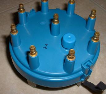
easy, wires and plugs easy; it�s the distributor I�ll cover quickly.� Look closely inside the distributor, inside
the lower and cap base, you will see the number 1 molded into the cap
and base.� These obviously indicate the
number one piston in the compression cycle.�
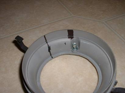
In the second picture you can see how I recommend marking the
distributor base.� First I highlight the �1,� then after I get the engine timing
set perfect I mark the actual setting with a short fat line that lines up with
the rotor.� Then I add a longer skinny
line that shows where the rotor should be pointed before the distributor is
dropped into the block.� All these marks
may seem like overkill, but it is my web site and these are the best ways to do
the job.
Before you
install the distributor make sure the engine is at TDC for cylinder one, and
you have mounted the TFI to the side of the distributor.� Drop the distributor so the rotor is aligned
with that 1 molded into the cap.�
Note that the actually positioning of the distributor to the block is
not important; we are aligning the rotor inside the distributor with that 1.� Make sure there is enough room to rotate the
distributor in the block 1/8th turn.� You
will need to rotate it to set the base timing of 10� before TDC
HOW
TO CHECK AND SET TIMING
1. Insure the key is OFF position
2. Place transmission in PARK or NEUTRAL, A/C and heater in OFF position.
3. Connect timing light.
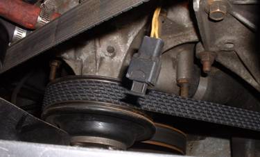
4. Disconnect the single wire in-line SPOUT connector or remove the shorting bar from the double wire SPOUT connector.� An example of a SPOUT connector is below:
5. Start the engine.� To set timing correctly a remote starter should not be used.� Use the ignition key only to start the vehicle.� Attaching a remote starter might disable or initiate the start mode timing after the vehicle is started.
6. Read the timing from the engine dampener on the crank.
7. If the timing does not read 10� before TDC continue to step 8, if timing matches 10� before TDC skip to step 10.
8. Shut engine OFF, and loosen distributor enough so you can twist it with your hand.� Do not loosen it to the point where the engine rotation moves the distributor.
9. Re-start engine and twist distributor to a point where 10 can be read aligned with the timing pointer.
10. Shut
engine OFF, reconnect SPOUT connector, and insure the distributor hold down
bolt is tight.
11. Re-start engine.
12. Check
timing advance to verify distributor is advancing beyond the initial
setting.� (This confirms Computer
control)
13. Shut off
engine and remove test instruments.
Exhaust
Exhaust is only a big
problem for some; they get close to finishing their giant EFI project and then
run into problems in the very end.� Try
not to get surprised this late in the game, look at your frame rails, firewall,
front drive shaft, and where you want the exhaust to go.�
�
Copyright 2003 Fordfuelinjection.com, a division of RJM
Injection.
Fordfuelinjection.com is not affiliated with Ford Motor Company.