Build Part 5
Engine Management
There are actually a good number of options for engine management available in the aftermarket world. Unfortunately, not all of them are really viable on a 2000 Subaru EJ251. In the end, I found a really good deal on a GReddy EManage Ultimate. Considered one of the better (if not best) piggy-back ECUs available. It's worth noting that I managed to pick up a EManage Ultimate with the model "e" layout. At the time, the model "d" was the more common. I just got lucky I think.
Wiring
In order to make the EManage easily removable I decided to employ a DB15 15-pin computer connector. I'll use a Male/Female pair put in-line in the main wiring harness, then a 2nd par wired to the EMU to match the wiring needs. This way, I only need to unplug the pair or DB15s from the EMU, and plug them back together to return to 100% stock ECU functionality. You might also consider using a a couple of 9-pin mini-DIN plugs. You'll need 2wice the plugs, but they are way smaller.
Cable Routing Configuration
- No EMU Installed
- Engine (DB15F) <-> ECU (DB15M)
- EMU Installed
- Engine (DB15F) <-> EMU (DB15M)
- ECU (DB15M) <-> EMU (DB15F)
- 4-pin Molex Power Plugged-in
Notes
- Don't tap the Knock sensor, the EMU doesn't play nice with the factory Knock system. If anything, use an aftermarket knock sensor.
- The EMU detects and calculates RPM from the ignition input signal. No need to tap the RPM wire.
- EMU Connectors
- 12-pin = Connector A
- 18-pin = Connector B
- 14-pin = Connector C
EMU Jumper Settings
- JP1-(Open) - Injector I/O ch1
- JP2-(Open) - Injector I/O ch2
- JP3-(Open) - Injector I/O ch3
- JP4-(Open) - Injector I/O ch4
- JP5-(Open) - Injector I/O ch5
- JP6-(Open) - Injector I/O ch6
- JP7-(1-2) - Ignition Input Signal
- JP8-(1-2) - Ignition Output Signal
- JP9-(Open) - Airflow Signal I/O
- JP10-(Open) - Airflow Signal Input 2 / VTec output
- JP11-(Open) - Option 1
- JP12-(Open) - Option 2
- JP13-(Open) - Knock 1 / Water Temp Input 1
- JP14-(Open) - Knock 2 / Intake Temp Input 1
- JP15-(1-2) - RPM Signal 3
- JP16-(anything/not used) VTech Freq Input
- JP17-(anything/not used) VTM Output
- JP18-(Open) - Injector I/O Signal 1-6
- JP19-(Open) - Injector Signal CH-A
- JP20-(Open) - Injector Signal CH-B
- JP21-(1-2) - Injector I/O Signal (1-6)
1 - Do NOT tap the Knock Sensor, the Subaru ECU can't share the signal. Some people reported the temp reading is decreased by 20oC if set to OPEN. This was not the case with my EMU. Perhaps it's been fixed in new versions.
2 - Not needed since the RPM is detected from the ignition input from the ECU.
Power & Ground for EMU
Tap/splice (don't cut) into the ECU power and ground wires and add the red and black wires from one end of a 4-pin Molex connector. Red for 12v, black for ground. Then, take the other end of the 4-pin molex pair, and wire the 12v and ground to the EMU. I left the other 2 wires intact but taped up and out of the way, just in case I found a future need for them. The other upside to using one of these molex connectors, is you can now find one of those molex Y-Adapters used to add an extra hard drive to a PC to create a 2nd Power/Ground pair for another device. Like a Wide-band O2 Controller module for example.
-
ECU/Engine Wire Harness
- B134-8/Ground (tap) -> Black wire of Molex Connector
- B135-7/12v (Ignition Power) (tap) to Red wire of Molex Connector
-
EMU Connector B:
- Pin-12(B)/Ground -> Black wire of Molex Connector.
- Pin-13(R)/12v -> Red wire of Molex Connector.
4-pin Molex Extension.
Just cut the wires in the middle.
Engine/ECU Harness to DB15F/F pair
Some of the connections between the engine and the ECU are cut and intercepted by the EMU, and others are simply tapped and referenced. However to keep things simple and clean, all wires in the harness, tapped or cut, will be cut. In order to achieve the equivalent of a tap, the wires at the EMU side will be joined together.
When Setting up the main splice, the above pins images will be used as reference. Note carefully the location of pin1 on the Male and Female DB15 connectors.
- 2000 Subaru 2.5L ECU Pin Reference (1)
- 2000 Subaru 2.5L ECU Pin Reference (2)
- 2000 Subaru 2.5L ECU Pin Reference (3)
The DB15 connectors will be positioned as follows inline of the main engine harness.
- DB15F on Engine Side of Harness
- DB15M on ECU Side of Harness
The following pins in the DB15 connectors will be connected to the identified ECU Harness wire.
- DB15-1 - B134-25 / Ignition ch1 for cylinders 1/2
- DB15-2 - B134-26 / Ignition ch2 for cylinders 3/4
- DB15-3 - B136-5 / Map Sensor
- DB15-4 - B136-17 / TPS Sensor
- DB15-5 - B134-4 / Injector 1
- DB15-6 - B134-13 / Injector 2
- DB15-7 - B134-14 / Injector 3
- DB15-8 - B134-15 / Injector 4
- DB15-9 - B136-29 / Atmospheric pressure sensor
- DB15-10 - B135-24 / VSS (Vehicle Speed Sensor)
- DB15-11 - B136-14 / Water Temperature
- DB15-12 - B136-13 / Intake Air Temperature
- DB15-15 - B134-7 / Injector Ground
EMU (DB15M) to Engine Harness (DB15F)
-
DB15M -> Connector A:
- DB15-2 -> Pin-11(Orange/Black) / Ignition Output ch2 - To Ignitor for cylinders 3/4
- DB15-1 -> Pin-12(Blue/Black) / Ignition Output ch1 - To Ignitor for cylinders 1/2
-
DB15M -> Connector B:
- DB15-3 -> Pin-3(White) / Airflow Input - To MAP/MAF sensor signal
- DB15-4 -> Pin-4(Gray) / TPS (tap)
- DB15-15 -> Pin-18(Black/Red) / Injector Ground (tap)
-
DB15M -> Connector C:
- DB15-9 -> Pin-1(White/Gray) / Analog input signal Atmospheric pressure sensor
- DB15-11 -> Pin-2(Blue/Yellow) / Water Temp (tap)
- DB15-5 -> Pin-4(Blue/Gray) / Injector Output Ch1
- DB15-6 -> Pin-5(Orange/Gray) / Injector Output Ch2
- DB15-7 -> Pin-6(Yellow/Graw) / Injector Output Ch3
- DB15-12 -> Pin-8(Purple/Yellow) / intake Temp Signal (tap)
- DB15-10 -> Pin-11(Lt.Blue/Yellow) / VSS Input
- DB15-8 -> Pin-12(Purple/Gray) / Injector Output Ch4
EMU (DB15F) to ECU (DB15M)
For pins on the EMU side that are identified as (tap) pins, a separate wire is soldered to the pin, and the other end is run and tapped to the actual EMU wire that is identified. If you notice the EMU Connector/Pin, it will match a Connector/Pin combo from above.
-
DB15F -> Connector A:
- DB15-2 -> Pin-4(Orange/White) / Ignition Input ch2
- DB15-1 -> Pin-5(Blue/White) / Ignition Input ch1
-
DB15F -> Connector B:
- DB15-4 -> Pin-4(Gray) / TPS (tap) - A wire separate Gray wire is run back and tapped to the actual EMU wire.
- DB15-5 -> Pin-5(Blue/Red) / Injector Input Ch1
- DB15-6 -> Pin-6(Orange/Red) / Injector Input Ch2
- DB15-7 -> Pin-7(Yellow/Red) / Injector Input Ch3
- DB15-8 -> Pin-8(Purple/Red) / Injector Input Ch4
- DB15-3 -> Pin-10(Green) / Airflow Output To Map sensor
- DB15-15 -> Pin-18(Black/Red) / Injector Ground (tap) - A wire separate Black/Red wire is run back and tapped to the actual EMU wire.
-
DB15F -> Connector C:
- DB15-11 -> Pin-2(Blue/Yellow) / Water Temp (tap) - A wire separate Blue wire is run back and tapped to the actual EMU wire.
- DB15-9 -> Pin-7(Green/Gray) / Analog Output signal for Atmospheric pressure sensor
- DB15-10 -> Pin-10(Brown/Yellow) / VSS Ouput
- DB15-12 -> Pin-8(Purple/Yellow) / intake Temp Signal (tap) - A wire separate Purple wire is run back and tapped to the actual EMU wire.
One bit at a Time!
This is, I think, the most important thing to do while installing your EMU.
DO NOT DO ALL THE CONNECTIONS AT ONCE, DO IT IN MANAGEABLE STAGES
I didn't just cut all the wires at once, and create every connection. I did it in easily understandable stages, and started the car after each one. That way, if the car failed to start, I knew where to look for the reason.
The following list shows what group of connections I modified during each phase. After each group was connected, I started my car, and check the EMU log screen to ensure it all looked fine.
- Ignition ch1 and ch2
- Map Sensor
- TPS Sensor
- All 4 Injector Signals
- Atmospheric pressure sensor
- VSS (Vehicle Speed Sensor)
- Water Temperature
- Intake Air Temperature
You can see the obvious benefit of doing this. If after connecting my TPS sensor, my car didn't start, yet it did start after my MAP sensor was connected, I knew exactly where to look for the problem!
Photos
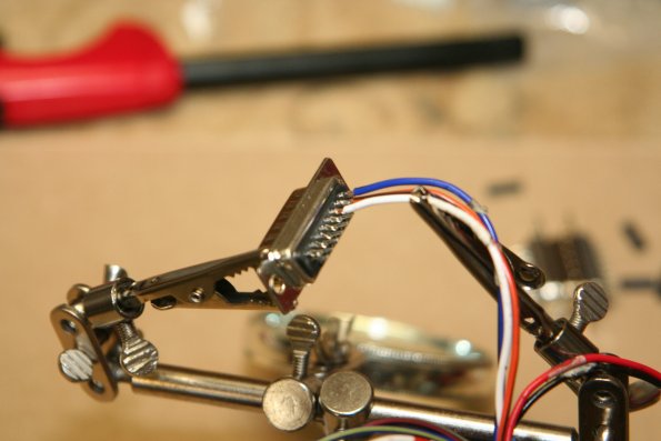
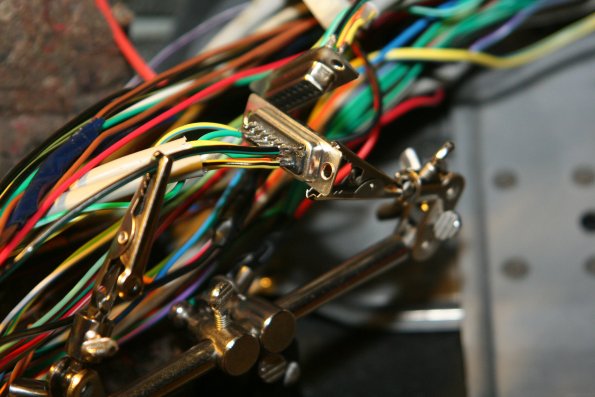
Clips holding the DB15 ready for solder
If you don't have one of these handy clip/helper doodads.. get one!
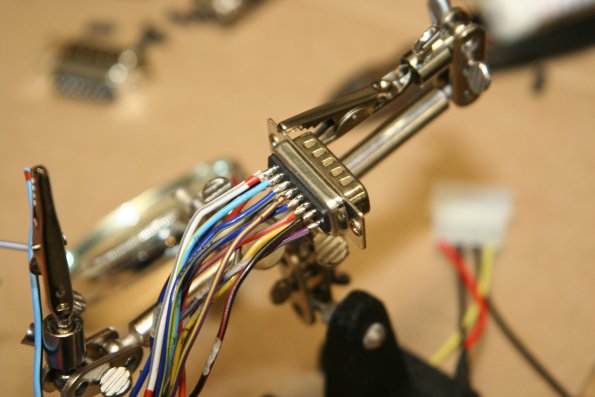
One DB15 done!
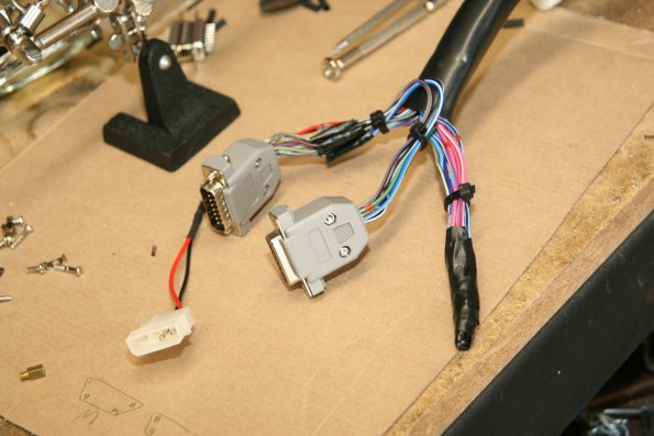
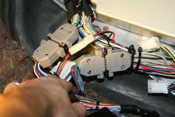
Both DB15s and the power Molex soldered to the EMU
Note the couple of wires that appear to loop back from one DB15 to the other.
These are the (tap) connections.
The wires do indeed run from one to the other, and also are connected back to the EMU.
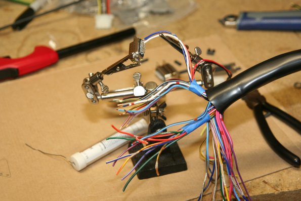
That clip doodad holder helped while soldering the ECU harness too
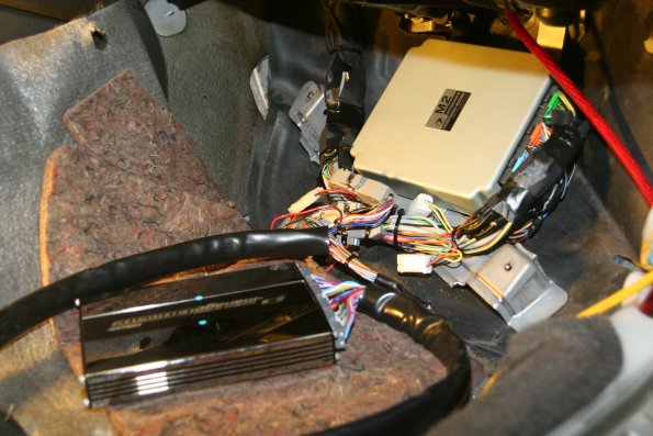
The EMU plugged into the harness.
The Final Result.
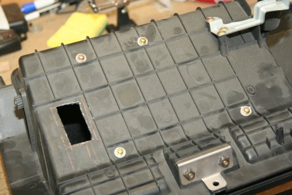
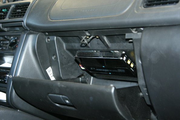
The EMU was installed to the roof of the Glove Box
Here are the screws on the back holding it in, and the wire access hole..
The EMU mounted and all buttoned up.
2 BAR MAP sensor
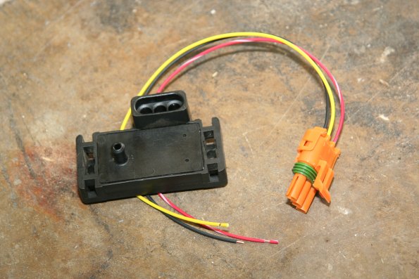
I found a document online about how to use a GM 2-bar MAP sensor instead of the rather pricey Greddy/TRUST sensor. So, I found a 2-bar GM MAP sensor, bought a pigtail harness for it. Why a GM 2-BAR Sensor instead of the GReddy Pressure Sensor? For 2 reasons, cost and range. The GM sensor is very common, and I picked up a used one for only $15. Plus, since I'll only be boosting to about 5-6psi, I don't need a pressure sensor that can read 30psi of boost. The 2-BAR sensor is good for up to 15psi of boost. The GReddy 3-BAR is good for 30psi of boost. If I used the 3-BAR I'd be wasting a large portion of the 0-5v output range for an area that I won't ever need/use. So, the 2-BAR sensor gives me a little better resolution.
On the GM MAP sensor, the 3 pins should be labeled A,B,C. It doesn't matter if using a 1,2 or 3 BAR sensor, they all use the ABC pins labels:
- A = Ground
- B = Signal
- C = 5v Input.
The EManage Ultimate can use either option port to read the MAP sensor. While looking at the EMUs option ports, the 3 pins from left to right (1,2,3) are:
- 1 = Signal
- 2 = 5v Output
- 3 = Ground
Used GM 2-BAR MAP sensor and new pigtail
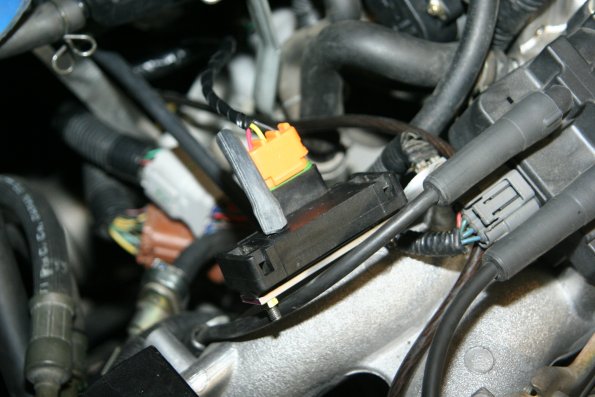
GM 2-BAR MAP sensor mounted to top of Intake Manifold
Reference
- GM Map Sensor Code Lookup
- 1 Bar: 039, 460, 883
- 2 Bar: 886, 012, 539, 609, 701
- 3 Bar: 749
- Subaru OEM Bosch 1bar MAP Sensor
- -0.46v = 0kpa (this was calculated given the known values below)
- 1.1v = 35kpa
- 4v = 100kpa
- [http://www.robietherobot.com/storm/mapsensor.htm Great GM MAP sensor Info]
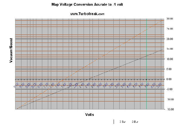
GM 2-BAR Map Sensor Volts vs Pressure Reference
This Word document I found online, although not from an Official GM source, appears to have the most detailed information about the Volts vs Pressure values of the 2BAR GM sensor.
| Volts | Relative PSI (boost) |
|---|---|
| 4.90 | 14.31 |
| 4.84 | 14.00 |
| 4.67 | 13.00 |
| 4.50 | 12.00 |
| 4.33 | 11.00 |
| 4.16 | 10.00 |
| 3.99 | 9.00 |
| 3.82 | 8.00 |
| 3.47 | 6.00 |
| 3.13 | 4.00 |
| 2.79 | 2.00 |
| 2.45 | 0.00 |
| 2.03 | -2.4(5 inHg) |
| 1.61 | -4.9(10 inHg) |
| 1.19 | -7.4(15 inHg) |
| 0.77 | -9.9(20 inHg) |
| 0.35 | -12.3(25 inHg) |
| 0.02 | -14.3(30 inHg) |
| Volts | PSI | kpa |
|---|---|---|
| 0.0 | 0 | 0 |
| 2.25 | 14.7 | 100 |
| 5.0 | 17 | 200 |
Reference
- http://www.sr20forum.com/turbo/133751-gm-map-sensor-emanage.html
- http://www.robietherobot.com/storm/mapsensor.htm
A/F
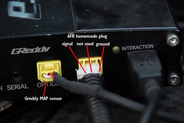
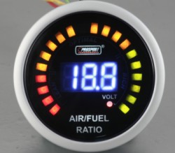
For Air/Fuel ratio monitoring, I choose the Innovate LC-1 Wideband controller. It's price and performance make it a popular choice. I also wanted to use this because it has 2 programmable output signals. I used one to feed a signal to the EMU, and the other to feed a signal to a ProSport Digital Wideband Gauge. I made a pair of EManage Option Harneses from 2 PC CDROM drive audio cables. There is a thread on NASIOC.com that outlines the DIY harness cables. The LC-1 wideband signal is fed into Option2 on the EMU through one of these home made cables.
The EManage Ultimate has a built-in setting to communicate with the Innovate LC-1. But, the LC-1 needed it's output signal modified for the ProSport gauge to read correctly. I programmed the LC-1 to output different voltage levels, and I read the resulting AF value on the gauge until I came up with the correct Volts:AF values.
- 0v = 10:1
- 5v = 20:1
Modified PC Audio Cable becomes AF Harness
Innovate LC-1 Wideband|ProSport Digital Air/Fuel Gauge
See above for an explanation of the EMU option port pins. The AF sensor requires the use of only 2 of the 3 pins.
- 1 = Signal
- 2 = not used.
- 3 = Ground
Gauges
Using the Subaru OEM center gauge housing, I managed to get 4 rather useful gauges installed. Since the OEM housing is really only sized to fit the smaller OEM gauges or the Omori <2" gauges (too expensive for me) I had to custom build a backing plate to hold the standard 2-1/16" gauges.
From left to right you can see the ProSport AF gauge in the separate cup pod, an oil pressure gauge, Vac/Boost gauge and an EGT Gauge. Photo Pending
Notes
I completely soldered both DB15s to the EMU wiring harness first. I double checked, tripple checked, and then re-checked both the pin locations, and even the wire color. Would you believe that the manual for the EMU actually had 2 errors in wire color! Then, once I was happy with the EMU, I soldered in the DB15s into the car one component at a time. I started with just the 2 ignition wires. Then I plugged in the EMU to see if it was working. Success. Next, I did the 4 injector wires and 1 ground. Then the TPS and MAP sensor. Then the temp sensors... etc... In between each component that I added, I started up the car to make sure everything was running normal.
Here is an interesting one. There were a few thread on NASIOC that claimed connecting the EMU to the Water Temperature and Intake Temperature sensors caused the signals to be skewed by -35C. This meant that while the engine was running at 80C, the ECU thought it was only at 45C. That's not good! So, I was very cautious as I added these 2 temp sensors. But, alas, I didn't have the same problem. Perhaps it's an issue with the particular sensors, or perhaps it's something fixed in the new EMU? Who knows.
Reference
- http://forums.nasioc.com/forums/showthread.php?t=1575752
- http://www.skyline-owners-club.com/forums/17660-emanage-ultimate-faq.html#post216829
- [http://www.innovatemotorsports.com/resources/news3.php LC-1 FreeAir calibration Trick]
- [http://www.innovatemotorsports.com/resources/news3.php How a Wideband works]
- [http://www.rs25.com/forums/showthread.php?t=70584 THE Brydon/Jefff install thread] - Contains the initial Brydon JP/Pin info
- [http://forums.nasioc.com/forums/showthread.php?t=1458449&page=4 Brydons NASIOC post]
- [http://forums.nasioc.com/forums/showthread.php?t=1626520&highlight=road+tune Good WRX tuning guide on nasioc]
### Things to know when setting up EMU
- RPM signal = Ignition signal
- TPS is normal on some cars and reverse on others so watch out.
- Setup DIP switches and make sure only two are on at any time. IE 1 Ignition and 1 fuel map.
- I/J lag time is ~0.7msec
- Ignition input and output only have 2 channels on the RS.
### Things to do even if you have a zero map
- Set All the cells in the Boost Limit Cut Setting map to 4.5 that way you don't get a cell when boosting and you directly control the injectors when in boost.
- In the Analog output setting map set the last 2 cells to 4.5 volts so you avoid a cell for the atmospheric pressure sensor while boosting.
### Good things to know
- Start by taking back 1 degree of timing for every psi of boost. You might even tapper this up higher as the rpms raise. Just for safety to begin tuning.
- Richen up the whole map tappering up while going into boost and while in boost. This way you are rich and since you control the injectors directly you will need more fuel as you get more boost. This doesn't mean these numbers have to be positive just more positive then cells that have less boost. Be aware that every number in your fuel map might be negative if you are using larger injectors.
well basically that's it!!! I run a piggyback on my RS and a standalone on my L. The difference is huge cams, huge turbo, and a car that mostly sees the track. The piggyback gets me to work everyday without fail. Starts well, runs smooth, and works well as a daily driver. The L actually starts, idles, and runs flawlessly but I had to put countless hours into it not to mention waiting for it to be colder or warmer to setup the enrichments and idle settings for whether conditions. Not exactly something you want to do on your daily driver.
Tuning
EManage_Ultimate_Injector_Scaling
Currently these are ONLY notes.
- If you are running boost you will have to pull back a little bit of mid range timing before it goes into open-loop link
- AFs of 10.5 - 11.0 are considered safe fat values for boosted EJ251s

